Part 1 in our GMAW series, Gas Metal Arc Welding Basics, Part 1: Welding Current and Voltage, discussed how variations in both welding current and welding voltage affect the penetration profile and bead profile of a weld. In this installment, the variables of travel speed and contact tip to work distance (CTWD) will be discussed in the same fashion.
These topics cover the four main variables of the gas metal arc welding (GMAW) process that affect both the penetration profile into the base material and weld bead profile that lies above the base material for a given weld:
- Welding Current
- Welding Voltage
- Contact Tip to Work Distance
- Travel Speed
Also known as metal inert gas (MIG) welding, basic GMAW processes allow for wide-ranging adaptability to ensure desired outcomes. Let’s see how these final two variables impact results.
The Effect of Travel Speed in Welding
In most cases, weld penetration into a base material is increased when the travel speed of a weld is increased, and vice versa. At slower travel speeds, the arc is directly above the center of the molten weld pool. Consequently, the metal that is transferred from the melting filler metal to the weld pool is deposited into the center of the weld pool. When the metal transfer happens in this centered fashion, the weld pool acts as a large cushion to the incoming metal droplets and reduces the degree to which the droplets penetrate into the base material.
Conversely, at faster travel speeds, the arc is typically at the leading edge of the weld pool resulting in the metal transfer droplets directly impacting some of the base material instead of just the weld pool. This more direct impacting into the base material results in deeper weld penetration as it limits the cushioning effects of the weld pool.
The welds show in Figure 1 & 2 show the relationship between travel speed and weld penetration into the base material. The welds were made at incrementally increased travel speeds yet at the relative same heat input. This was done in attempt to keep the weld deposit size of each weld bead relatively the same. Weld 30 through Weld 34 had increased travel speeds and consequently increased penetration into the base metal. The weld data for these welds is shown in Table 1.
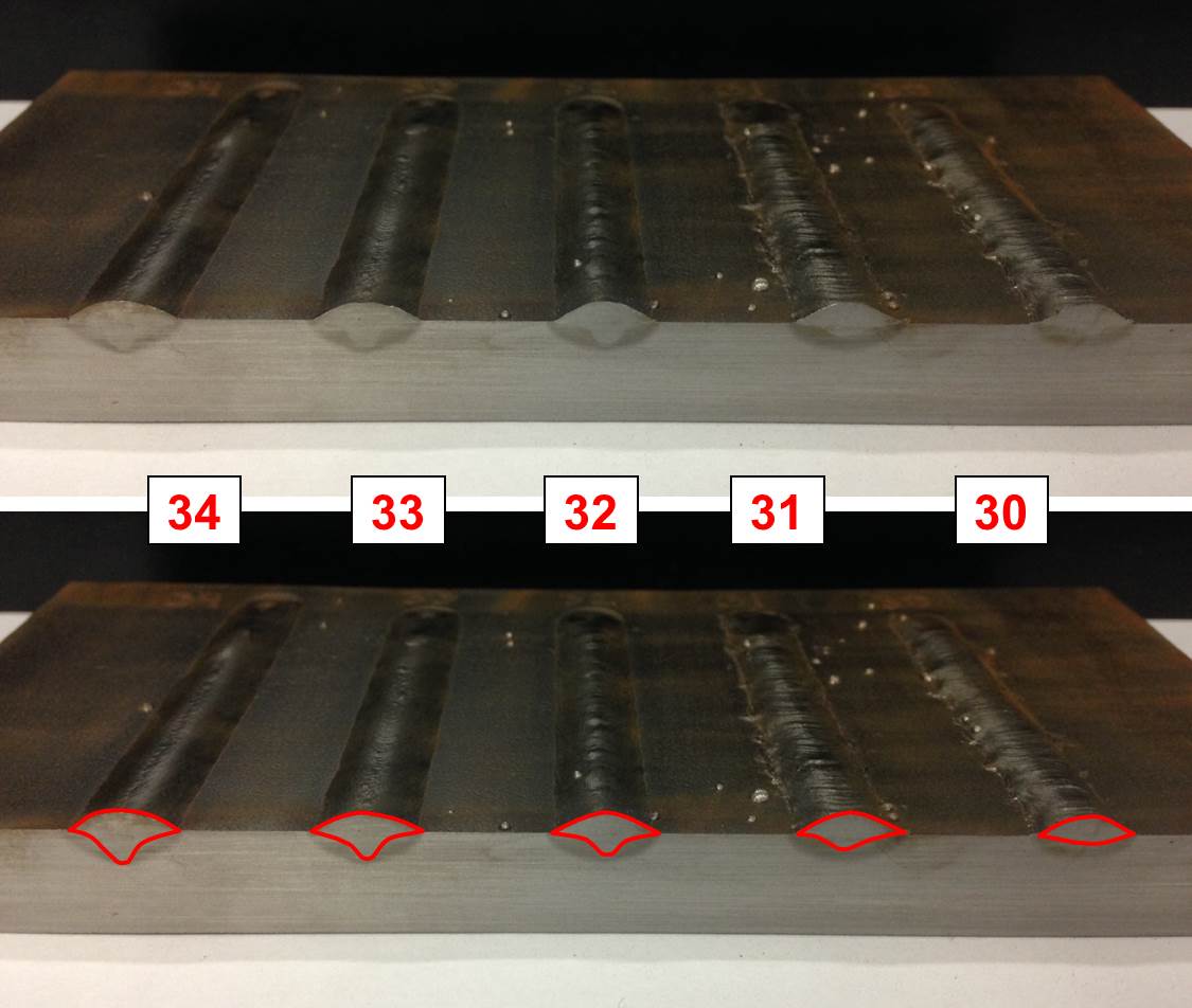
Figure 1: Cross-sectional View of Welds 30-34. Red outline better displays the penetration profile.
Slower travel speeds result in a solidification pattern that is circular or oval. Faster travel speeds result in a solidification patter that is circular on the leading edge but V-shaped on the trailing edge of the weld pool. Note the variation in solidification pattern of each bead outlined in red on Figure 2.
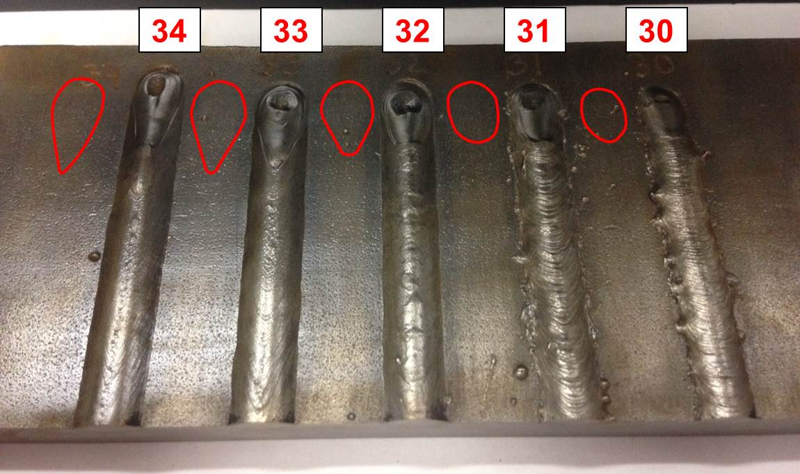
Figure 2: Topside View of Welds 30-34
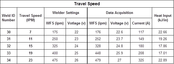
Table 1: Travel Speed Data (with Wire Feed Speed and Voltage Chart)
GMAW Contact Tip to Work Distance
As discussed in Part 1 of this series, GMAW process commonly uses a constant voltage power source (GMAW-CV) that allows for a relatively constant welding voltage output over a range of welding currents. For GMAW-CV, the welder selects the wire feed speed (WFS) on the wire feeder unit and an appropriate voltage on the welding power supply. The internal circuitry of the power supply then supplies an appropriate amount of welding current necessary to maintain a stable arc. The GMAW process variables of current and wire feed speeds are interrelated so one cannot be independently adjusted without affecting the other by just altering the WFS selector setting on the power supply itself.
One common way to independently manipulate the welding current from the WFS is by adjusting the contact tip to work distance (CTWD). This phenomenon understood by applying Ohm’s law, V=IR (V=voltage, I=current, and R=resistance), to the electric extension segment of the welding wire, Figure 3.
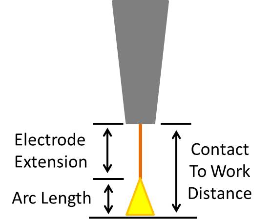
Figure 3: Electrode Extension, Arc Length, and Contact Tip to Work Distance Diagram
Since we want to see the effect of CTWD variations on welding current, let’s rearrange the equation to I=V/R. Assuming the use of a constant voltage power supply the V (volts) will remain a constant in this equation. The diagram on the left of Figure 4 suggests a baseline CTWD. If then, the CTWD is increased the electrode extension will also increase since the constant voltage power supply will maintain a consistent arc length despite the change in the CTWD. The increase in electrode extension length has an associated increase in resistance as the effective ‘conductor’ length has increased. According to Ohm’s law, assuming a constant voltage, current and resistance are inversely proportional to each other so the increase in resistance will result in a decrease in current.
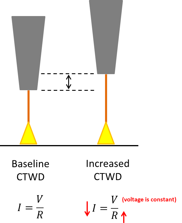
Figure 4: CTWD Variation Diagram
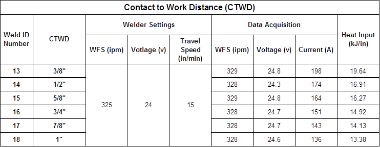
CTWD should follow Ohm’s Law, and this is exactly what was seen in Welds 13 – 18. As the CTWD was incrementally increased for each weld, the welding current decreased, all the while maintaining the same WFS. The weld data from these trials is shown in Table 2.
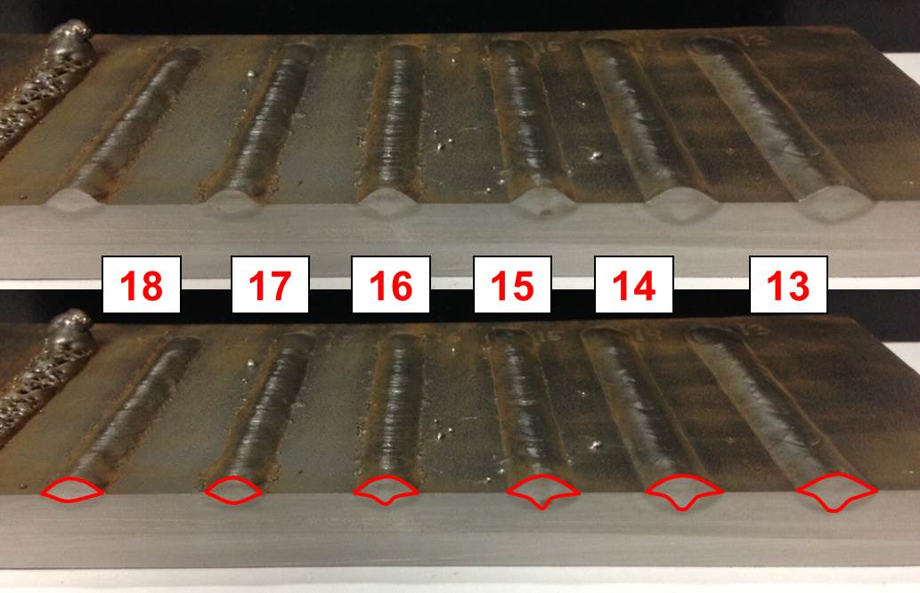
Figure 5: Cross-sectional View of Welds 30-34. Red outline better displays the penetration profile.
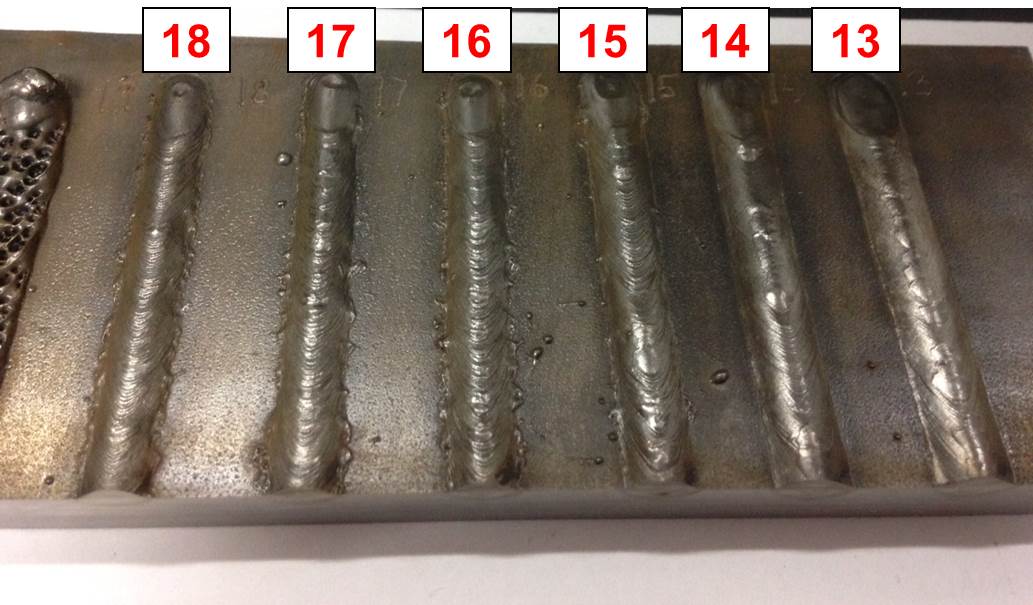
Figure 6: Topside View of Welds 30-34
Table 2: Contact Tip to Work Distance Data
Take a Closer Look with EWI
From GMAW basics to pioneering joining solutions, EWI customers and members get the support and insight they need to improve manufacturing results. Ready to learn more about GMAW at EWI?
Questions? Contact Michael Carney, EWI Senior Engineer, at [email protected].