When using a consumable-electrode process such as gas metal arc welding (GMAW) or submerged arc welding (SAW), the three primary process variables are arc current, wire feed speed (the rate at which the consumable electrode is fed from the welding torch), and arc voltage. Current and wire-feed-speed cannot be varied independently. To maintain the same voltage and arc length, a change in one will always require a change in the other. Increasing the wire feed speed will require an increase in current since a greater volume of electrode material must be melted per unit of time.
The most straightforward method of increasing the productivity of a process is to increase the deposition rate. The deposition rate is directly related to the wire feed speed since the majority of this material is deposited into the weld pool. Unfortunately, this increased deposition rate requires an increase in current, which leads to increased heat input and increased penetration. When welding heat-input sensitive materials or for cladding operations where minimal dilution is required, these increases may not be acceptable. One technique to achieve higher deposition rates while minimizing increases in heat input and penetration is to use the phenomenon of resistive heating to your advantage.
Before describing the role of resistive heating in consumable-electrode arc welding processes, a clarification of arc welding terminology is required. The distance from the end of the contact tip to the base material is often referred to the contact-tip-to-work distance (CTWD) or the “stick-out.” An important distinction must be made between these two terms as they are often incorrectly used. The CTWD is the distance from the end of the contact tip and the base material, and is made up of the welding arc and the “electrical stick out” as depicted in Figure 1.
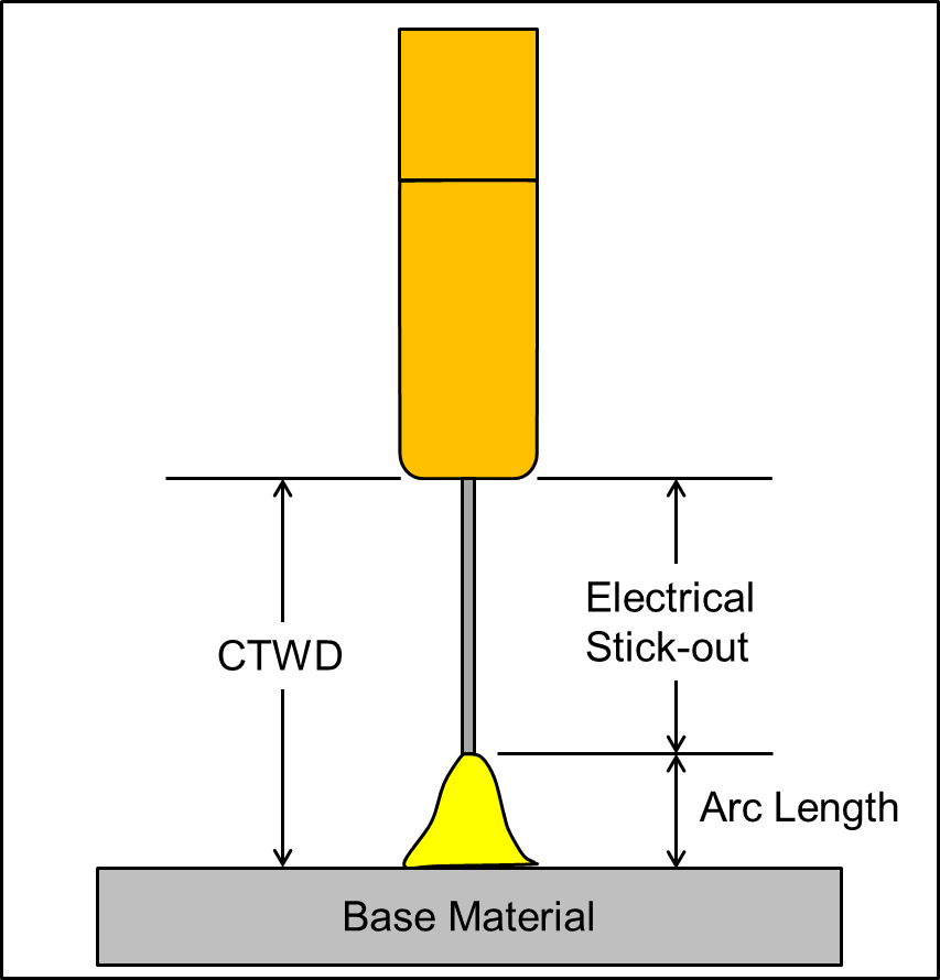
Resistive heating of a consumable electrode occurs within the length of the electrical stick out due the large amount of current passing through the wire. The inherent resistivity of the wire causes it to heat up, and reduces the amount of current required to actually melt a segment of the wire once it reached the welding arc. This effect is more effective for smaller-diameter wires which have a higher electrical resistance.
Due to the effect of resistive heating, increasing the CTWD will:
- Decrease the current needed to melt a consumable electrode fed at a given deposition rate
- Increase the deposition rate at the same current level
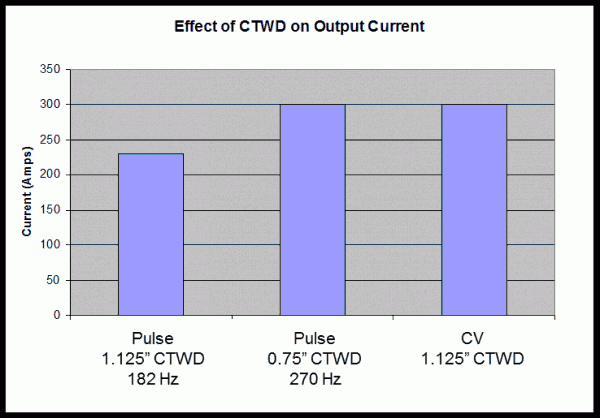
The first of these two effects is clearly illustrated in Figure 2. A pulsed GMAW (GMAW-P) weld was made with a CTWD of 0.75 inches and a wire feed speed of 200 inches per minute (ipm), resulting in a deposition rate of 10 pound per hour (lbs/hr) and a current of 300 amps. The CTWD was then extended to 1.125 inches, resulting in a 25% decrease in current to 225 amps. A third weld was made at the extended 1.125 inch CTWD in CV mode. The current increased to 300 amps, demonstrating the effectiveness of GMAW-P in reducing the amount of arc energy required at a given deposition rate.
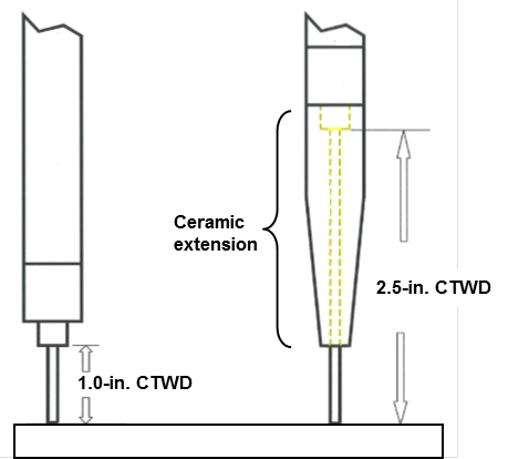
The maximum CTWD which can be used is dependent on a number of factors including wire diameter and the level of wire cast. For larger diameter wires, a large increase in the CTWD is possible, and is often required to see a significant effect due to the lower resistivity in an electrode with a larger cross-sectional area. To maintain wire straightness at these long CTWDs, commercially-available ceramic extensions can be used as pictured in Figure 3.
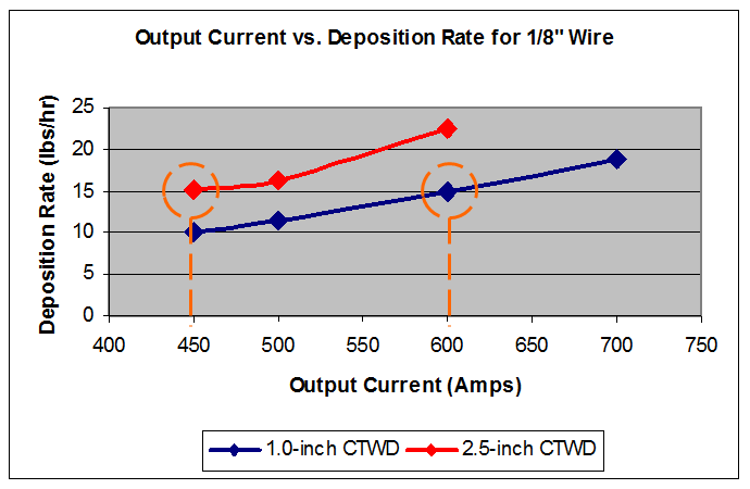
The effect of a 1.5 inch increase in the CTWD using a ceramic tip extension is shown in Figure 4. At a constant deposition rate of 15 lbs/hr, the current was reduced by 25% from 600 amps to 450 amps, resulting in a significant decrease in heat input. It is expected that this decrease would also result in a significant decrease in penetration. The graph also shows that at a given current level and heat input, using the ceramic extensions increased the deposition rate by approximately 50%
What makes this green? By using this technique we can put down more material for the same amount of energy.
For more information contact [email protected].