For nearly a century, gas metal arc welding (GMAW) has been a mainstay of industrial fabrication. In this GMAW overview, we cover a range of topics that are critical to understanding and achieving potential applications from a detailed gas metal arc welding definition to the difference between GMAW and FCAW.
What Is Gas Metal Arc Welding?
Gas metal arc welding (sometimes referred to as MIG) is a welding process that has been commercially available for around 60 years. The basic operation of the GMAW process occurs when an electrical arc is established and maintained between a base material and a continuously feed wire electrode. The molten weld pool is shielded from the atmospheric conditions by an envelope of shielding gas that is flowed continuously around both the wire filler metal feeding in the weld pool and the weld pool itself.
The heat of the electrical arc serves to locally melt the base metal as well as melt the wire filler metal that is being fed into the weld. There are two entities at play in the GMAW process:
- Burn Rate: This refers to the rate, inches/minute (in/min) or meters/minute (m/min), at which the wire filler metal is melted or consumed by the thermal energy of the welding arc. The primary variables that control the thermal energy of the arc are the welding current, voltage in welding, and GMAW gas type (composition).
- Feed Rate: This simply refers to the rate, again in in/min or m/min, that the wire filler metal is feed into the weld.
For a stable welding arc, the burn rate and feed rate need to equal each other. For instance, if the burn rate is higher than the feed rate, the wire filler metal would melt back to the contact tip and cause issues. With the exception of short circuit metal transfer, if the feed rate is higher than the burn rate, the wire filler metal would feed into the molten weld pool, again, causing issues.
There are four main variables of the GMAW process that affect both the penetration profile into the base material and weld bead profile above the base material for a given weld:
- Welding Current
- Welding Voltage
- Contact Tip To Work Distance
- Travel Speed
The information below observes the very basic effects that the GMAW current and GMAW voltage variables have on the weld penetration profile in the base material and the weld bead profile that lies above the base material. The base material used for the following welds is cold-rolled 1018 bar stock, and the shielding gas is 90% Argon – 10% CO2.
GMAW Basics with Constant Welding Voltage
The GMAW process commonly uses a constant voltage welding power source (GMAW-CV) that allows for a relatively constant welding voltage output over a range of welding currents. For GMAW-CV the welder selects the wire feed speed (WFS) on the wire feeder unit and an appropriate voltage on the welding power supply. The internal circuitry of the power source then supplies an appropriate amount of welding current necessary to maintain a stable arc. The GMAW process variables of current and wire feed speeds are interrelated so one cannot be independently adjusted without affecting the other by just altering the WFS selector setting on the power supply itself.
Effect of Welding Current on Metal Transfer in GMAW
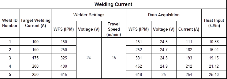
The variable of welding current (or amperage for welding) primarily controls the amount of weld metal that is deposited during welding. As discussed earlier, the process variables of WFS and current are directly related so as one increase so does the other and vice versa. Welds 1-5 demonstrate this relationship, Figure 1 & 2. Holding all other variable constant, the WFS was incrementally increased from Weld 1 through Weld 5 which consequently increased the welding current. Remember, the welder sets the WFS not the current level on a GMAW-CV power supply, so the primary way of adjusting current is by adjusting the WFS. Table 1 shows the welding data from these welds.
The welding current also affects the weld penetration profile. Holding all other variables constant, as the welding current increases the further the weld will penetrate into the base material. This increase in weld penetration is seen in Welds 1-5, Figure 1. The fingerlike penetration in Welds 3-5 demonstrates the effect of welding current on metal transfer in GMAW. The metal transfer mode typically transitions from globular to spray mode transfer above approximately 190 amps of welding current for certain metal and shielding gas combinations.
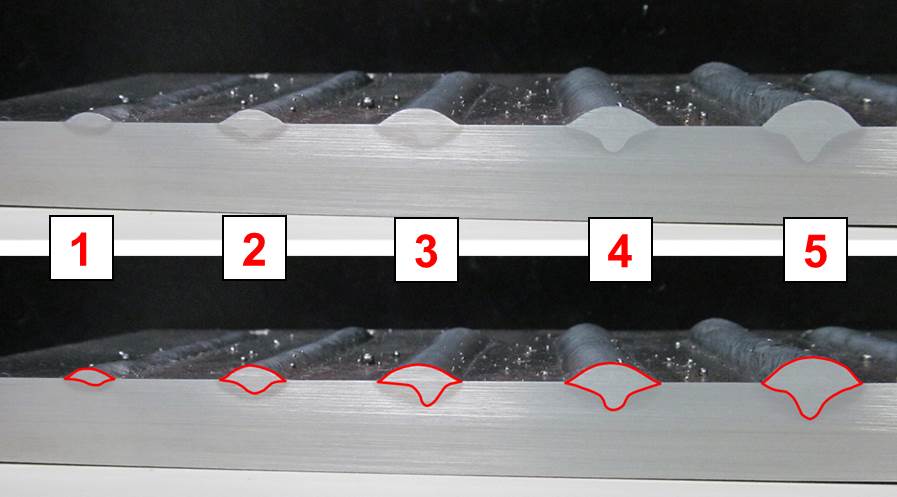
Figure 1: Cross-sectional View of Welds 1-5. Red outline better displays the penetration profile.
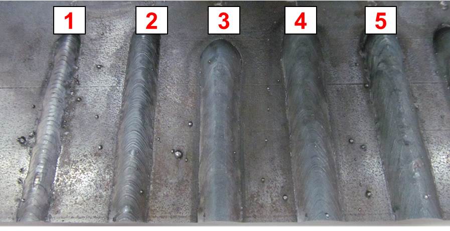
Figure 2: Topside View of Welds 1-5
Table 1: Welding Current Data
The Effects of Welding Voltage
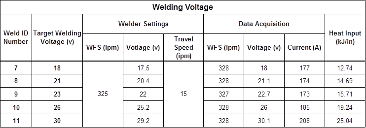
Welding voltage primarily controls the arc length in welding, which is the distance between the molten weld pool and the wire filler metal at the point of melting within the arc. As the voltage is increased, the weld bead will flatten out more and have an increasing width-to-depth ratio. Welds 7-11 in Figure 4 show this widening of the weld beads as the voltage is increased. Table 2 shows the weld data for these welds.
Note that the penetration remained relatively constant for Welds 7-9. Despite the change in voltage, the welding current did not change therefore weld penetration did not appreciably change. Welds 10 & 11 both exhibited an increase in fingerlike penetration as well as in increase in welding current. As the arc length increases proportional to an increase in voltage, the electrode extension distance from the contact tip to the point where the welding wire is melting in the arc, consequently decreases, Figure 3.
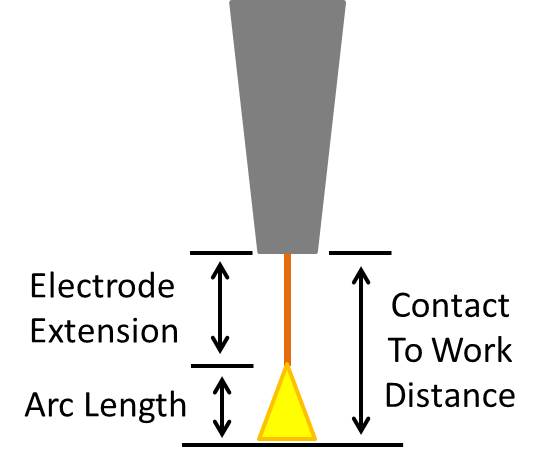
Figure 3: GMAW Electrode Extension and Arc Length Diagram
As the electrode extension decreases, so also does the resistance to the welding current flowing through that portion of the wire. Using Ohm’s law and holding the voltage constant, the welding current would consequently increase. The current was indeed increased and enough so to change the transfer mode from globular to spray which is evidenced by the increase in fingerlike penetration. This phenomenon is further explained in a separate article, Gas Metal Arc Welding Basics, Part 2: Contact Tip to Work Distance (CTWD) and Travel Speed.
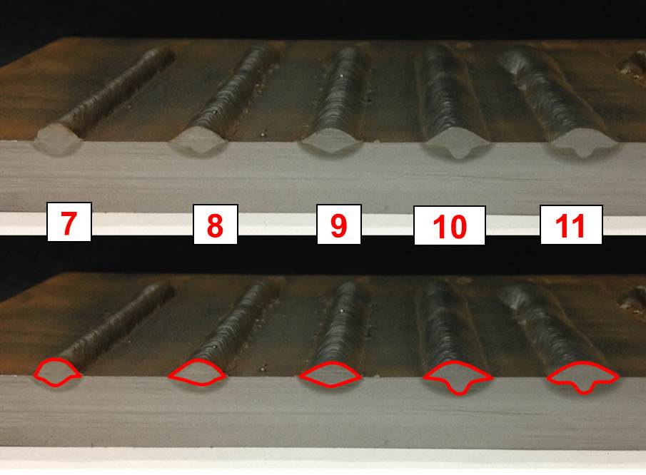
Figure 4: Cross-sectional View of Weld 7-11. Red outline better displays the penetration profile.
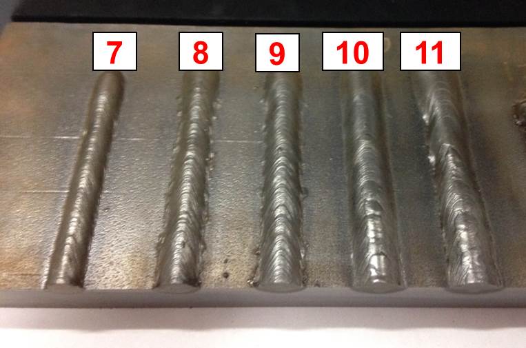
Figure 5: Topside View of Welds 7-11
Table 2: Welding Voltage Data
More About the GMAW Process
There’s more to explore. In our follow-up post, we look at the variables of contact tip to work distance (CTWD) and travel speed and observe how they affect the weld bead profile and base material penetration.
Check out EWI’s arc welding capabilities as well as our cooperative research program. If you have any questions about GMAW basics and innovations, contact Michael Carney at [email protected].