Reciprocating wire feed gas metal arc welding (RWF-GMAW) is a low heat input, precisely controlled variation of the GMAW process. With the RWF-GMAW process the wire is reciprocated in and out of the weld pool. The wire motion is synchronized with the current waveform to produce a weld that is characterized as having minimal if any spatter, and very controlled heat input, bead placement, and base metal dilution. Manufacturers of RWF-GMAW equipment include Jetline Engineering (Controlled Short Circuit (CSC)), Fronius (Cold Metal Transfer (CMT)), SKS Systems (micro-Mig), and Panasonic (Active Wire Process (AWP)). The purpose of this article is to describe the reciprocating wire feed gas metal arc welding (RWF-GMAW) process and to provide examples of applications where this variation of the GMAW process may be advantageous.
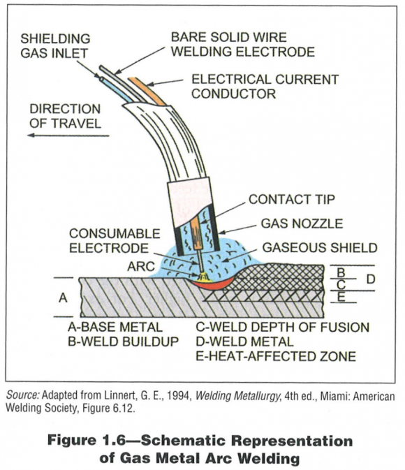
The gas metal arc welding (GMAW) process is a fusion welding process that produces coalescence of metal using the heat from an arc between a continuously fed consumable electrode wire and the base metal. An illustration of the GMAW process is shown in Figure 1. Electrical contact is made to the consumable electrode wire at the contact tip. A stream of shielding gas is fed through the nozzle and displaces the atmosphere in the vicinity of the arc and the weld pool. In addition to preventing atmospheric contamination of the weld pool and the heated consumable electrode wire, the shielding gas also provides the medium for current flow (i.e. the arc).
Figure 1. Illustration of the GMAW process
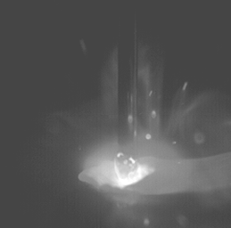
For conventional GMAW there are four primary modes of metal transfer: short-circuit transfer, globular transfer, spray transfer, and pulse spray transfer. Short-circuit transfer has historically been the GMAW mode used for applications requiring low heat input, low distortion, and/or small weld size. With the short-circuit mode the current level is not sufficient to maintain an arc or to enable transfer of droplets across the arc. The droplet forms on the end of the wire and is transferred to the weld pool when the wire with molten droplet come into contact with the weld pool. When the wire with molten droplet comes into contact with the weld pool, an electrical short is created and the current spikes. The combination of surface tension forces and the magnetic pinch force created by the current spike cause the droplet to transfer to the weld pool and the arc is reestablished. This process repeats itself about 100 times per second. The short-circuit mode can be used to produce relatively low heat input welds, with lower distortion levels than that achievable with other GMAW modes. The process uses conventional GMAW equipment and has a limited number of controls, making it very user friendly. However, because of the violent nature of the short-circuiting event, the process mode is characterized as having high spatter levels. The short-circuit mode also has a tendency for incomplete fusion discontinuities when welding thicker materials and is not allowed by several codes.
Figure 2. High speed video image of a short-circuit transfer weld made with conventional GMAW equipment
Several manufacturers have advanced versions of the short-circuit mode that enable more controlled droplet transfer, more precise bead placement, and reduced spatter levels. These advanced versions control the current waveform throughout the stages of the short circuit transfer cycle. Specifically, when the wire with molten droplet is in contact with the weld pool, the current increase that occurs is controlled so that spatter resulting from the clearing of the short circuit is reduced. These advanced short circuit transfer modes are deployed for many applications including those that have historically used short-circuit transfer GMAW but desire lower spatter levels, and root pass welding in the pipeline industry. Both the conventional and advanced short circuit modes are most often deployed semi-automatically. The advanced short circuit modes are insensitive to changes in the contact tip-to-work (CTWD) distance making them ideally suited for semi-automatic operation.
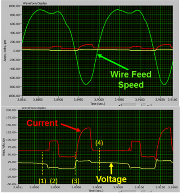
With RWF-GMAW the wire is reciprocated in and out of the weld pool in synchronization with the current waveform. This process is an even more controlled variation of the GMAW process because of the synchronization between the wire feed and the current waveform. Plots of wire feed speed, current, and voltage verses time for a weld made with Fronius’s CMT mode are shown in Figure 3, while high speed video images of a CMT weld are shown in Figure 4. During the arcing phase a droplet is formed on the end of the wire. The wire is retracted and then moved toward the weld pool. The shorting phase begins when the wire and molten droplet come into contact with the weld pool. The current first increases slightly, and then reduces to a minimum value. The retraction of the wire, in combination with the surface tension forces cause the droplet to detach. After the droplet detaches an arc is formed and the cycle repeats itself. Similar wire feed speed, current, and voltage waveforms are expected for RWF-GMAW welds made with other manufacturer’s equipment. With the RWF-GMAW process there is no current spike when the wire and molten droplet come into contact with the weld pool. With both the conventional and advanced short circuit modes droplet transfer is achieved through the combination of the pinch force imposed by an increased current level and surface tension forces. With the RWF-GMAW mode the current isn’t used to transfer the droplet, rather the droplet is transferred through the combination of surface tension forces and the mechanical retraction of the wire.
Figure 3. WFS, current, and voltage verses time for a weld made with a Fronius CMT system (numbers in parenthesis correspond to images shown in Figure 4)
Figure 4. High speed images of a t-joint fillet weld made with a Fronius CMT system (image numbers correspond to the waveform location in Figure 3)
The RWF-GMAW process has very low spatter levels when setup correctly. For many applications the RWF-GMAW process will produce no visually observable spatter. The process is capable of heat input levels ranging from less than 1-kJ/in up to heat input levels approaching that of the GMAW-P mode. WFS settings commonly range from 35-in/min up to several hundred inches per minute. In addition to its low heat input and low spatter characteristics, the RWF-GMAW process is capable of producing low dilution levels and precise bead placement. The RWF-GMAW process is more complex than the conventional and advanced short-circuit modes. A given wire feed speed setting can have 11 or more parameters associated with it. Many equipment manufacturer’s offer pre-canned programs that enable synergic control of the welding program. These pre-canned programs can be used in the as-received condition, or the background parameters can be tailored for the specific application. Modification of the background parameters is often required for difficult applications. The RWF-GMAW process is most commonly applied as a mechanized or automated process rather than a semi-automatic process. RWF-GMAW equipment is also more expensive than the equipment required for the conventional and advanced short-circuit modes.
Due to the added complexity and cost, the RWF-GMAW process is most often utilized for applications that warrant its positive attributes. For the majority of the applications that EWI has applied this process for, the reasons for evaluating the RWF-GMAW process were due to one or more of the following process characteristics: 1) low heat input, 2) low and controlled base metal dilution, and/or 3) precise bead placement.
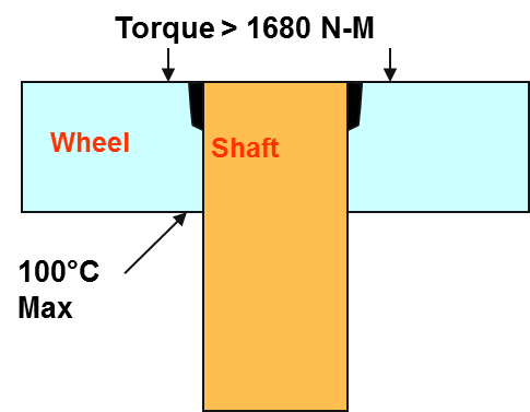
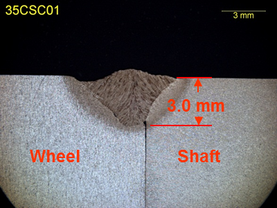
The RWF-GMAW process has been applied for automotive applications where it’s low spatter and low heat input characteristics result in less spatter and distortion. The RWF-GMAW process was evaluated as an alternative to GTAW for titanium sheet metal applications because the RWF-GMAW process has adequate arc stability and spatter characteristics with much lower heat input and distortion levels. EWI has also applied the RWF-GMAW process as an alternative to shielded metal arc welding (SMAW) for the fabrication of thick section weldments made from crack sensitive steels. Procedures were developed for the RWF-GMAW process that produced welds that met the ASME Section IX qualification criteria while providing increased travel speed (and production rates) and crack-free heat affected zones. EWI applied the RWF-GMAW process to the wheel to shaft joint illustrated on the left in Figure 5. This application utilized a partial penetration, narrow joint configuration. The weld was required to penetrate to the root of the joint, have complete sidewall fusion, withstand a torque of 1680-N/m, and due to an o-ring on the backside of the wheel, the maximum temperature on the backside of the wheel was limited to 100-deg C at any time. EWI developed RWF-GMAW procedures that met these requirements.
Figure 5. Illustration of the wheel to shaft weld joint (left) and a macrograph of the welded joint (right)
EWI has applied the RWF-GMAW process for numerous other applications that are proprietary to the project sponsors. Many of these applications have involved non-ferrous high alloy materials that are sensitive to heat input and dilution and require precise bead placement with no spatter. The RWF-GMAW process can produce welds with quality comparable to that of the GTAW process, at production rates characteristic of the GMAW process. The ability to produce welds with low and controlled heat input has enabled this process to be successfully used to weld crack-sensitive materials. The RWF-GMAW process should be considered for applications that require one or more of the following attributes: low and/or controlled heat input, low and/or controlled base metal dilution, precise bead placement, and spatter free welds.
For more information on the RWF-GMAW process, contact Nick Kapustka at 614.484.7600 or [email protected]

